How to Set Up ESP32 with Arduino IDE: A Beginner's Guide to Blinking Your First LED
Learn how to set up your ESP32 board with Arduino IDE and run your first program to blink the onboard LED. This beginner-friendly guide includes step-by-step instructions, download links, and troubleshooting tips to get you started with ESP32 in no time.
Alright, so I've got the whole kit for ESP32, but don't worry if you don't have the kit. Because in this article, we just need ESP32 board.
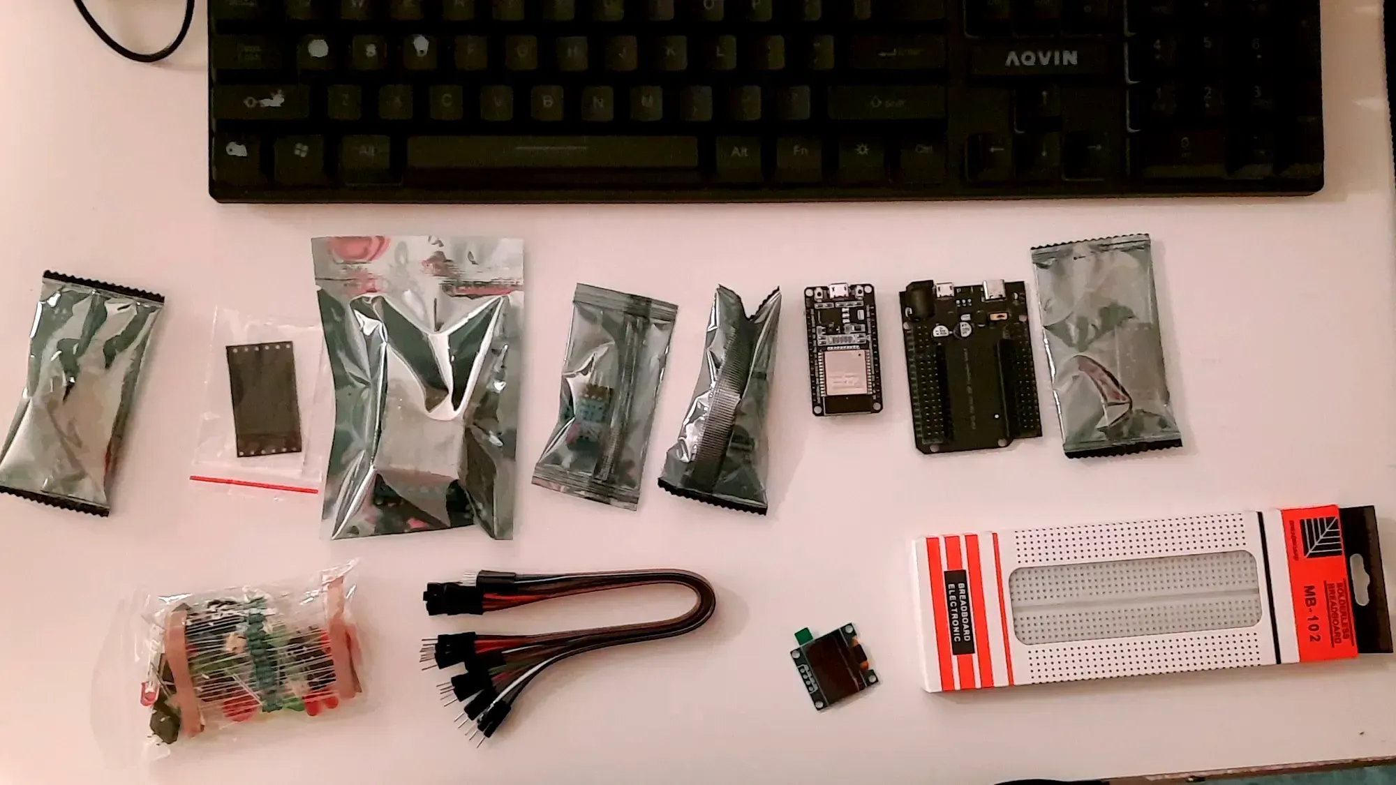
All you need to get started is a computer, an IDE, where you write and edit your code, and ESP32.
The board that I am using looks like below.
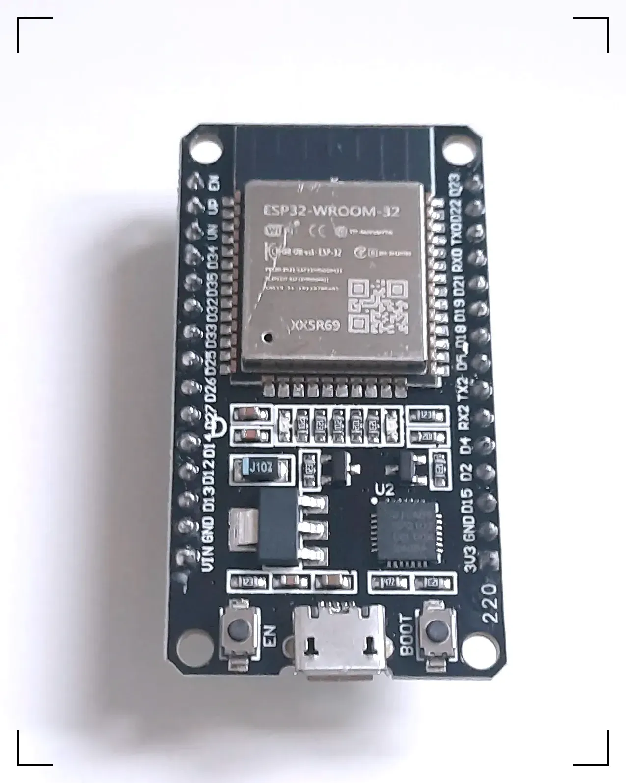
Set up Arduino IDE
We are not using Arduino boards, we just need IDE, and then we will select the board that we are using. So, just head over to https://www.arduino.cc/en/software and download the installer based on your computer system. I am using Windows 11, so I will download windows installer.
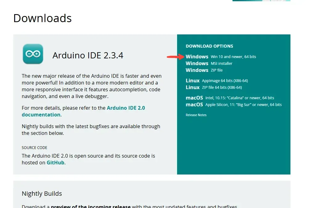
Once you download the file, simple double click and install it.
Once it is installed, you can run it, maybe restart the IDE a couple of times if you'd like.
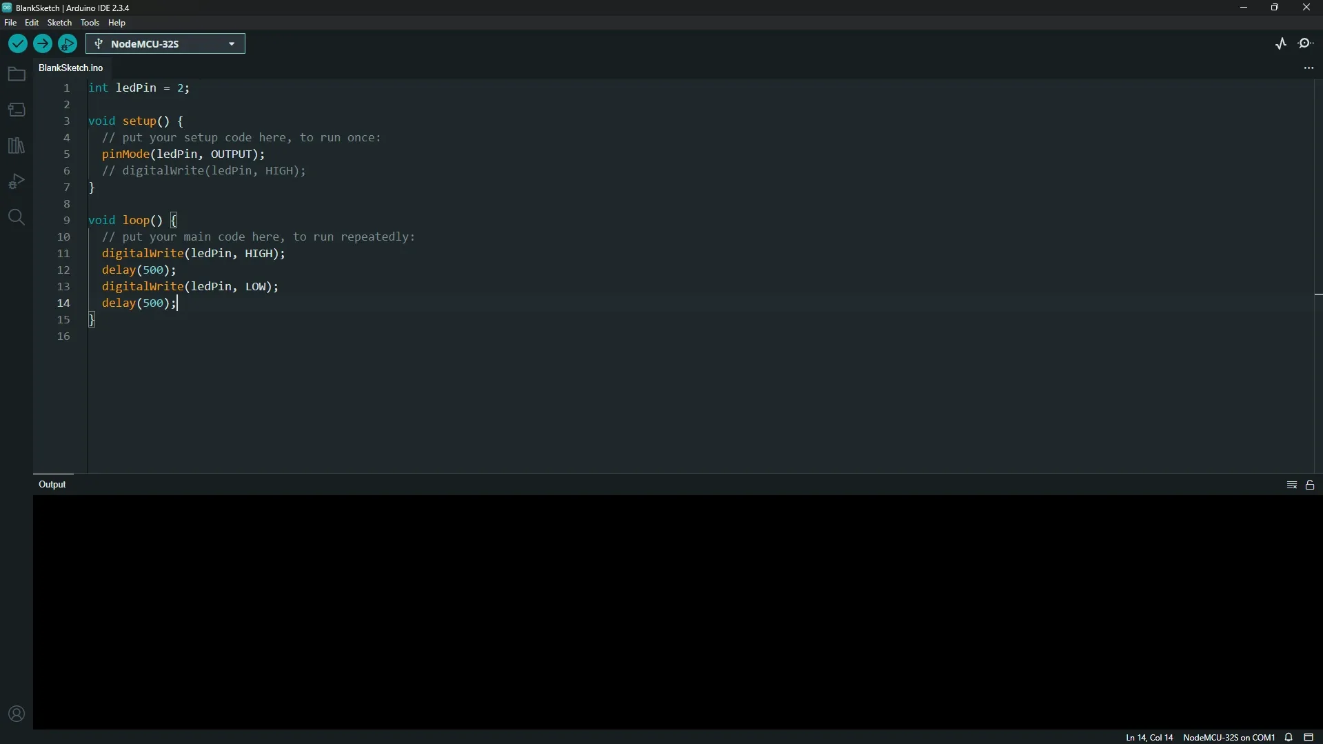
Of course, you won't have this code, but it looks similar to this.
Next step is to add ESP32 module.
Add ESP32 module in Arduino IDE
Add ESP32 Board Manager
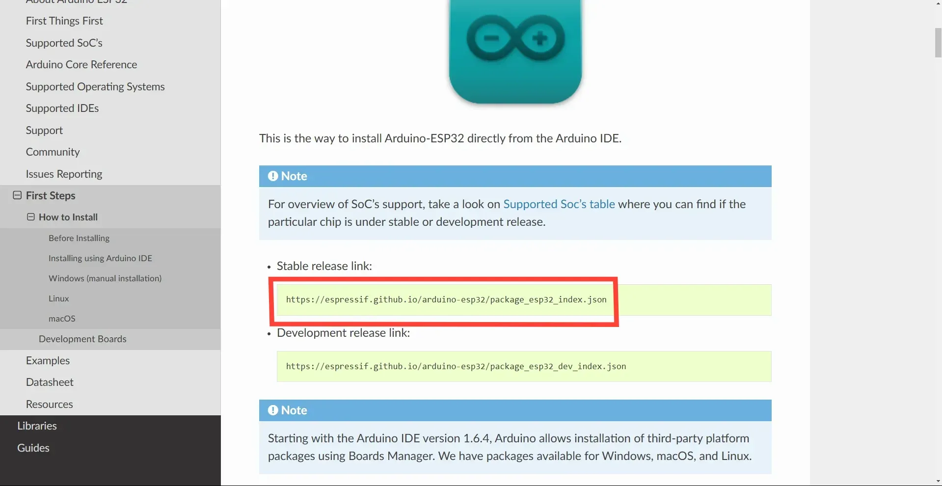
Head over to https://docs.espressif.com/projects/arduino-esp32/en/latest/installing.html and copy the Stable Release Link.
As of now, the stable release link is https://espressif.github.io/arduino-esp32/package_esp32_index.json
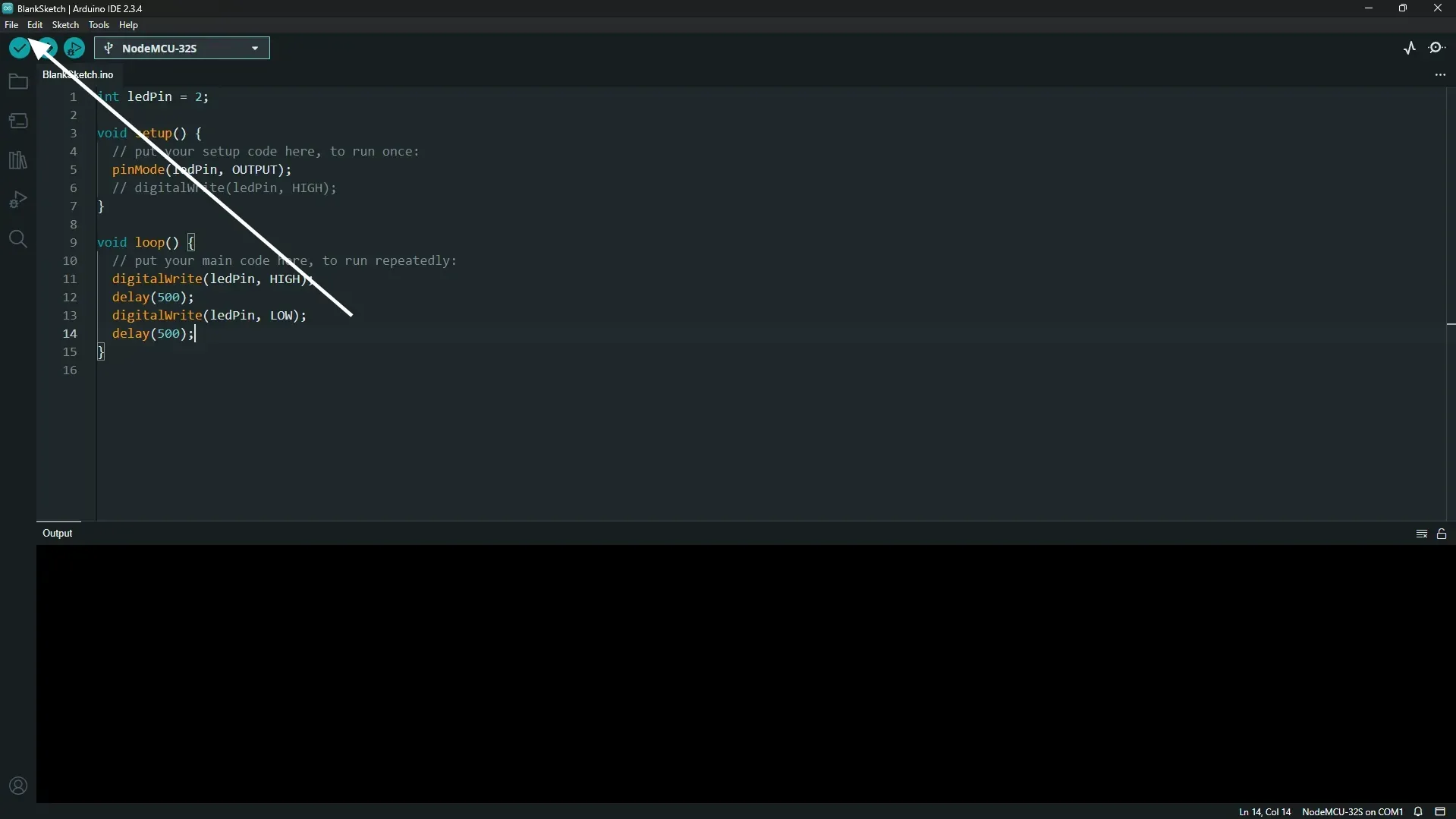
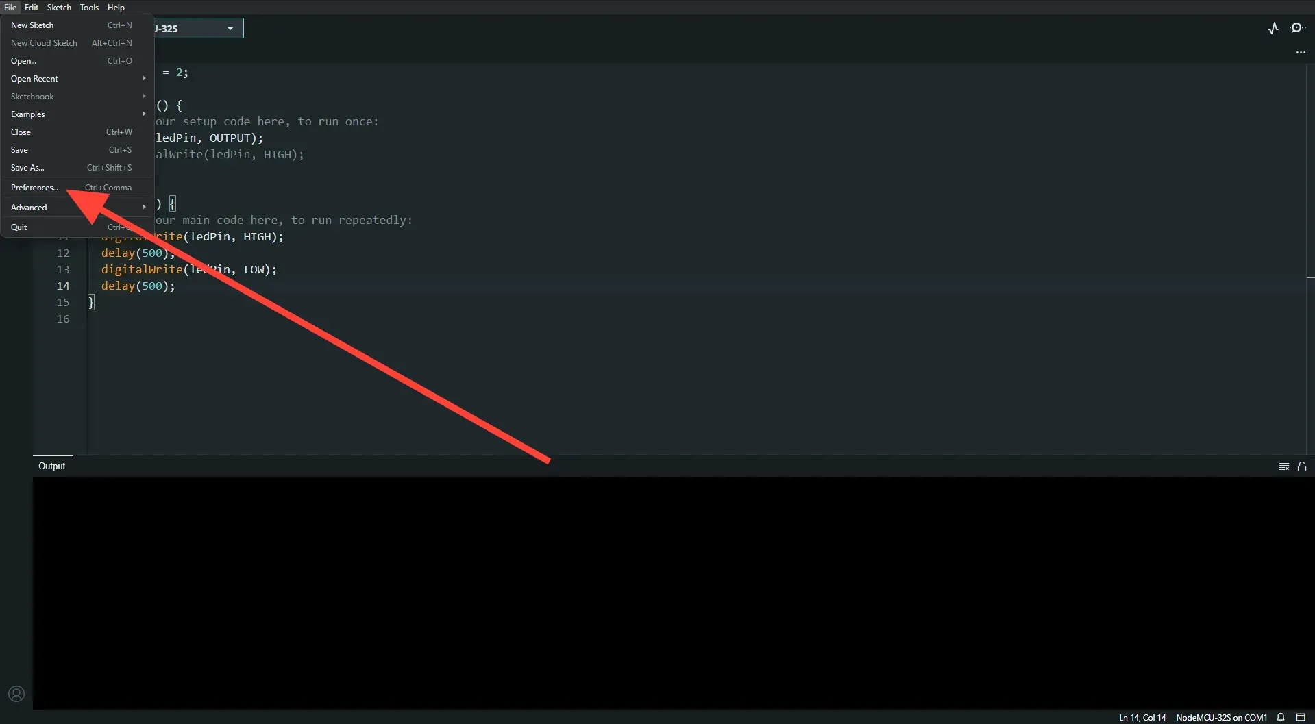
Then in IDE, go to File => Preferences. And add Additional Boards Manager URLs.
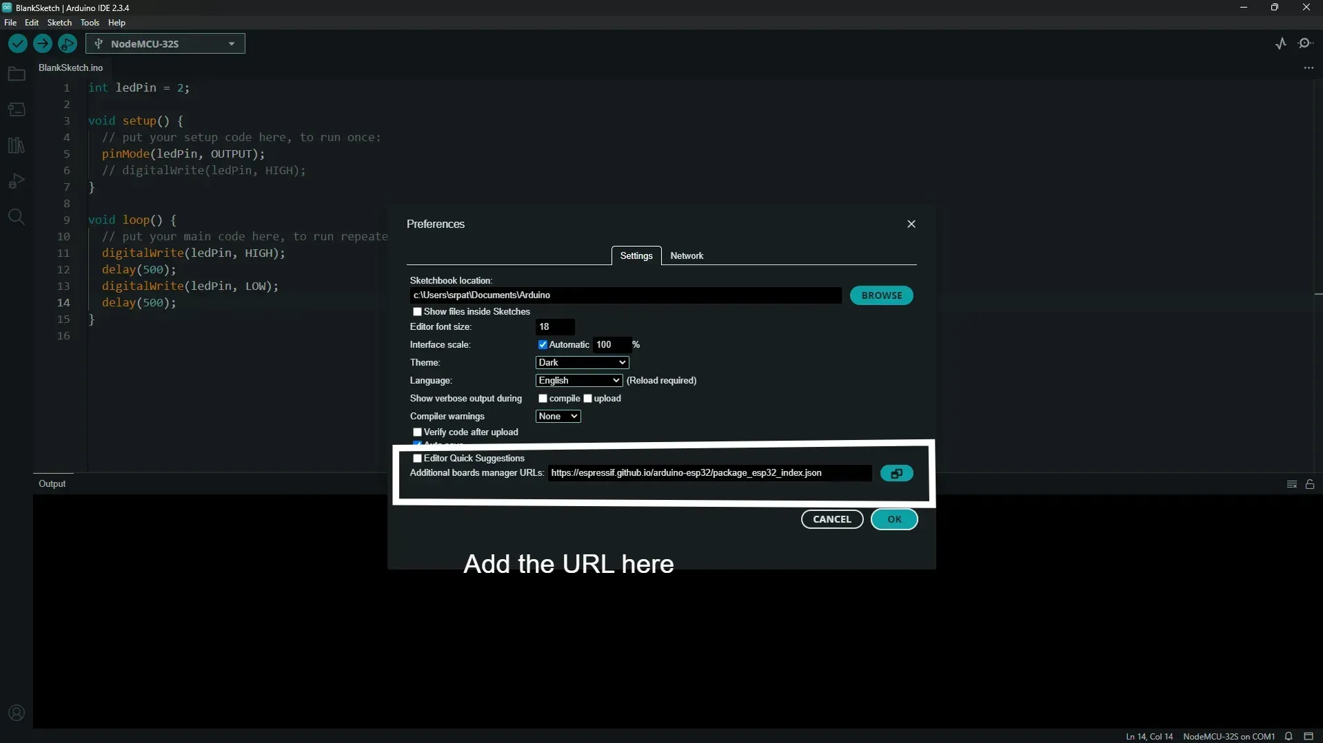
You might have to change the file location, in that case just choose a location that you won't be disturbing in the future.
Choose the installed ESP32 board manager
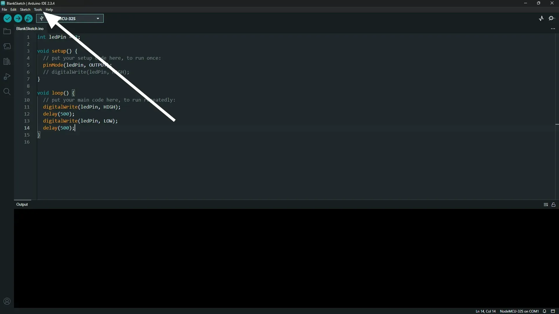
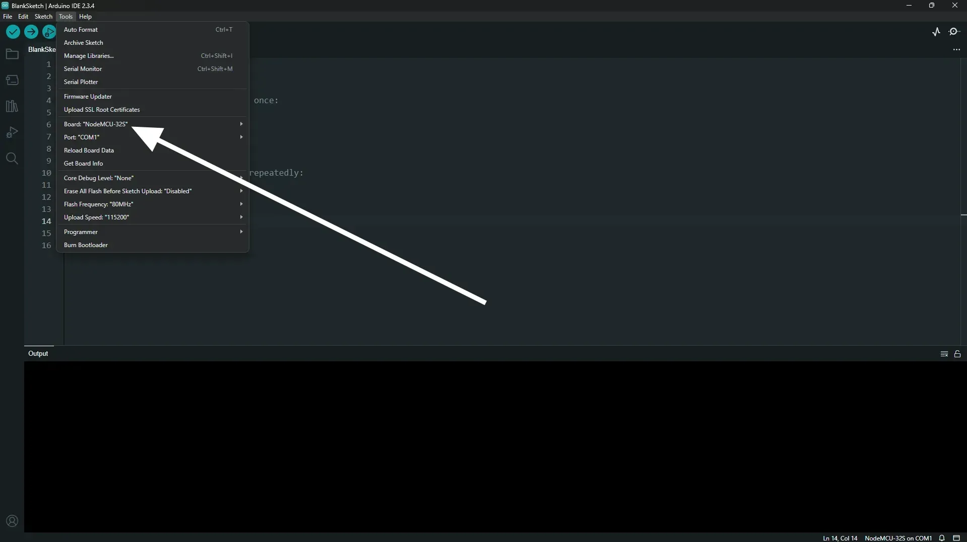
Go to Tools => Board => Boards Manager.
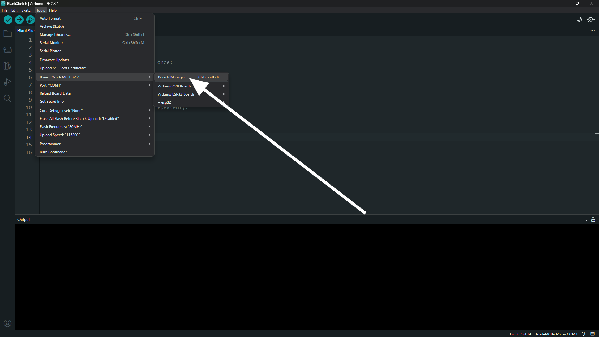
Then Search "esp32", and install the one by "Espressif Systems".
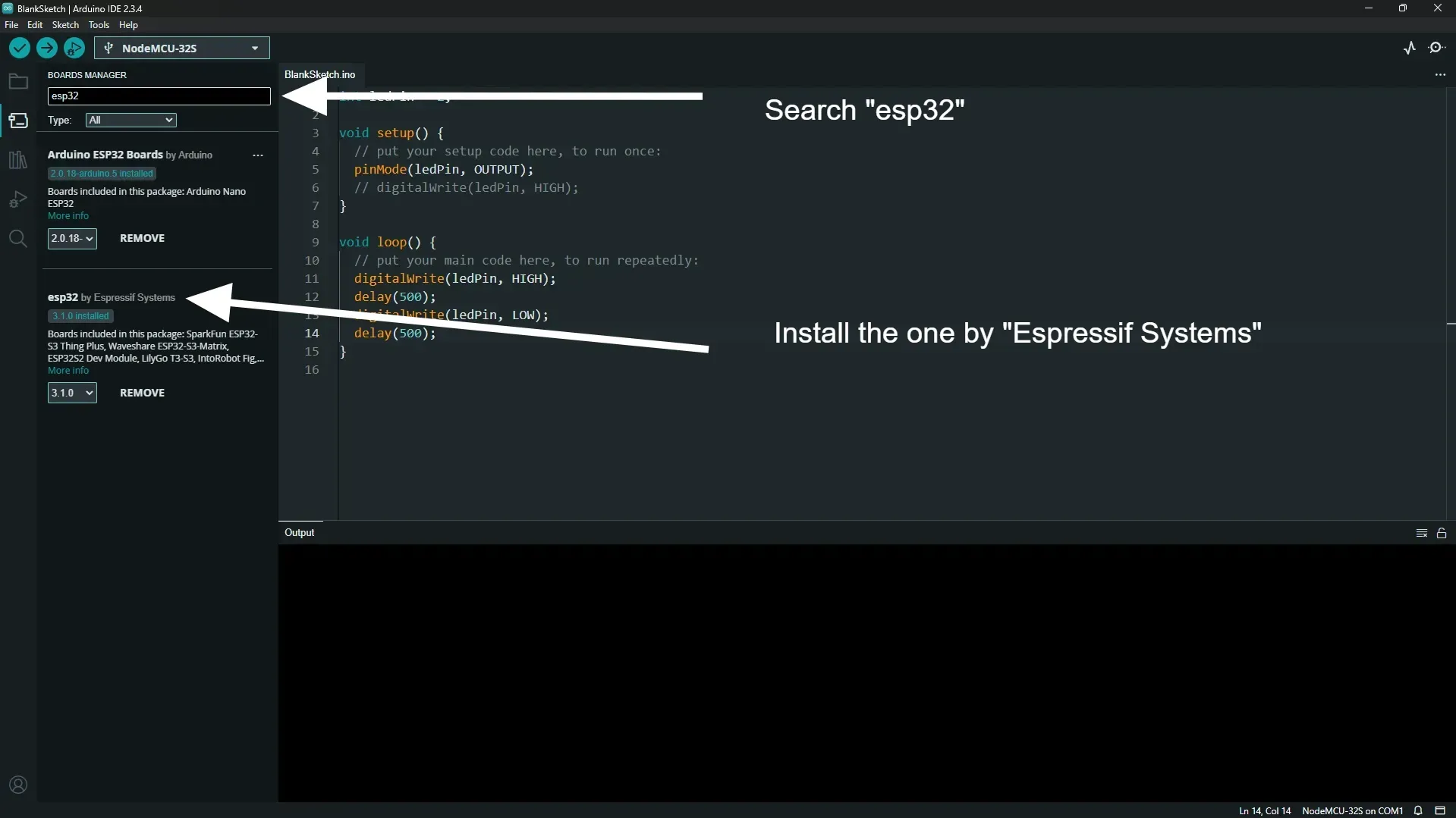
It takes a couple of minutes to install.
Select the board
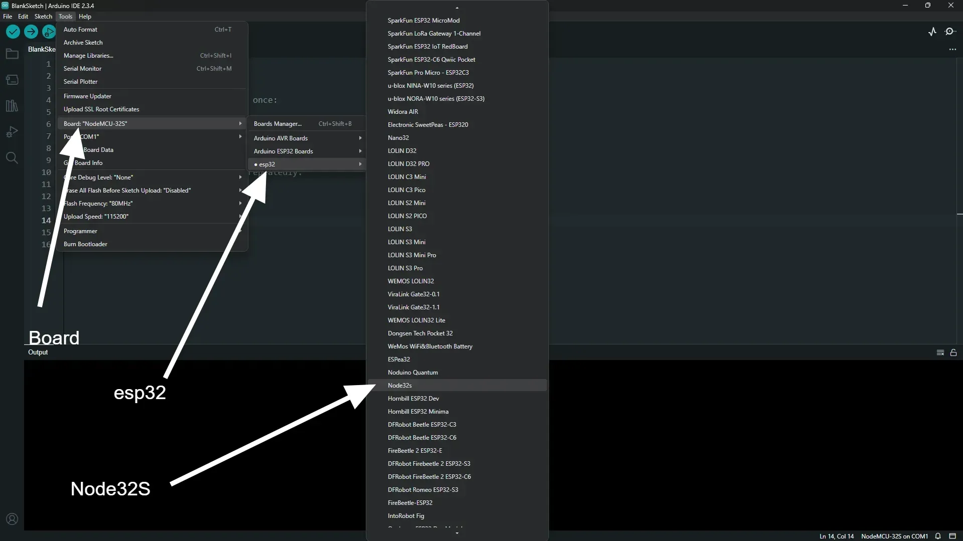
Go to Tools => Board => esp32 and choose "Node32S".
Select the port
Before selecting the port, plug in the ESP32 board with your computer, otherwise it won't work.
Go to Tools => Port. Then choose the port named "COM 3".
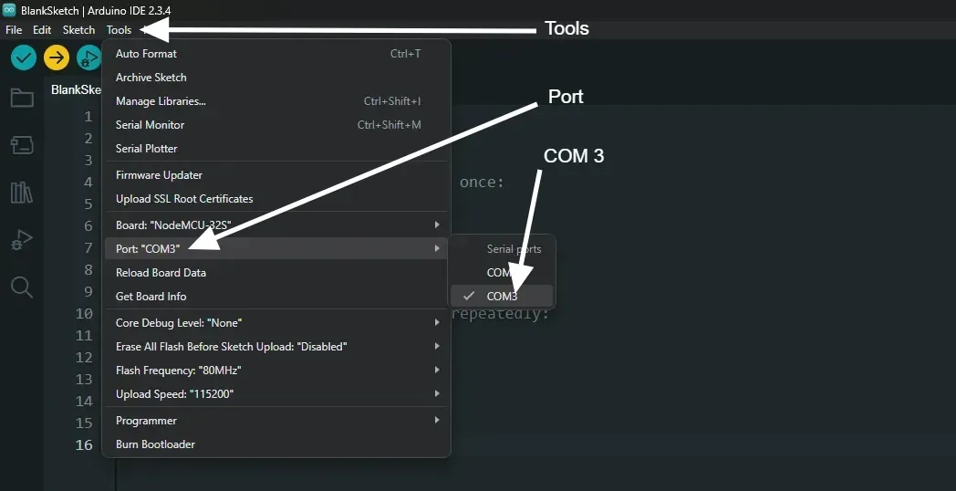
If you only have "COM 1" option available, it means you need a driver, which can be found here: https://www.silabs.com/developer-tools/usb-to-uart-bridge-vcp-drivers?tab=downloads
Simply install the driver, maybe restart the computer and then you can select the "COM 3" port.
That's it.
Write the code, and run it.
You don't need any wires and sensors to run this code. This code simply blinks the inbuilt LED, that is right on the board itself.
Here is the code.
int ledPin = 2;

void setup() {
  // put your setup code here, to run once:
  pinMode(ledPin, OUTPUT);
}

void loop() {
  // put your main code here, to run repeatedly:
  digitalWrite(ledPin, HIGH);
  delay(1000);
  digitalWrite(ledPin, LOW);
  delay(1000);
}
Then click on the Upload button.
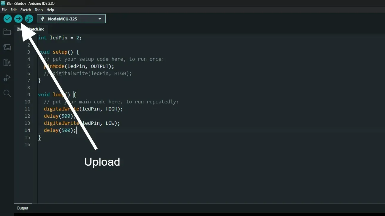
That's it, you should see the ESP32 board with a blue light blinking after every second.
We'll understand the code in the next article.